Index
Test machines
|
|
|
|
|
|
|
|
|
|
|
|
|
|
|
|
|
|
|
|
|
|
|
|
|
|
Test ancillaries
|
|
|
|
|
|
|
|
|
|
|
|
|
|
Measurement
|
|
|
|
|
Production
|
|
Services
|
|
|
|
|
|
|
|
Miscellaneous
|
|
|
|
|
|
|
|

Site Updated
2 February 2017
Solid state control and measurement electronics for Amsler Vibrophore
load control, single DPM version QT1000
|
Introduction
Si-Plan Electronics Research Ltd has been building and fitting control electronics to update Amsler Vibrophore frames for over 20 years. The present systems offer solid state computer compatible control and measurement electronics with load signal conditioning and single DPM display. Features Dynamic load Static load (tension or compression; automatic or manual control) Number of fatigue cycles (from 100 to 100 million) Trip zones |
|
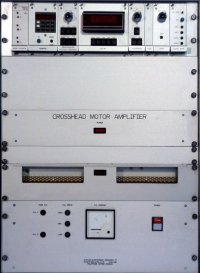
A free-standing 19" cabinet houses the main system elements:
|
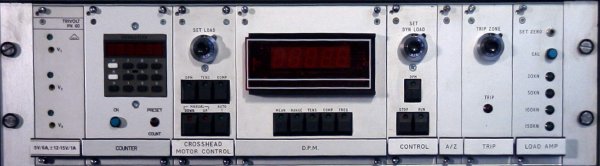
The instrumentation rack consists of 8 modules: |
|
Power Supply Module
The power supply is 55W ±14volt and 5 volt output for the instrumentation electronics. Counter Select the number of fatigue cycles to which the specimen is to be subjected. Any number of cycles from 100 to 100 million may be pre-set by means of the push buttons on the front of the counter and the decade switches below. Crosshead Motor Control Module Controls the static load applied to the test specimen by either manual or automatic control. In manual mode the operator depresses either the UP or DOWN button and observes the static load being applied to the test piece as indicated on the DPM module. In the automatic mode the operator sets the required load on the control marked SET LOAD, selects either TENSION or COMPRESSION using the selector switch next to the SET LOAD control and then depresses the AUTO ON button. The AUTO ON, UP and DOWN buttons are illuminated when that parameter is being used. In the case of auto operation the UP and DOWN lights will illuminate only when the motor is being used so that when the set point is achieved both will be extinguished. A remote manual control is also supplied, connected to the control electronics via a 4m cable. DPM Module A 4.5 (19999 fsr) digital panel meter (DPM) to indicate the load and test frequency applied to the test specimen. Select the parameter to be displayed on the DPM by depressing the appropriate buttons. Control Module Used to set the level of dynamic load -peak to peak load - at which the operator requires the specimen to be tested.. The dynamic load is set independently of the static load Auto Zero Module Stores the machine settings at start up (immediately the RUN button is released) so that the trip module is automatically referenced to the required static and dynamic loads. Trip module Compares the current dynamic and static load with the initial values stored by the autozero module. Stops the machine if the current values vary from the set value by more the the amount set with the TRIP ZONE control. Load Cell Amplifier Module with multiple channel auto select This module contains the strain gauge amplifier, bridge supply and associated range selection to scale the output voltage of a range of load cells to the correct level required by the control system. The load cells will be typically 20-200KN. This module also contains precision shunt calibration resistors. The control cabinet also houses: Twin 400W Power Amplifier This amplifier is connected to a matching transformer which is in turn connected to the AC excitation coil of the electromagnet in the load frame. The two 400W amplifiers are precisely matched and are working in parallel to provide 1400W peak power in the exciter coil when large or power absorbing specimens are being tested. Crosshead Motor Amplifier The high current drive amplifier for the crosshead motor, providing precise control of the static load applied to the specimen when the auto button is depressed. Power Unit This unit contains DC power supplies for the control coil of the electromagnet in the load frame and the power amplifier matching transformer. Features: Optional extras |
Updated 20 April 2005