|
|
Home
Index
Test machines
Test ancillaries
Measurement
Production
Services
Miscellaneous
|
|
|
Bearing test rig
|
Details
Electric Motor
- A 7.5 kW 2 pole Asynchronous induction motor fitted with an optical encoder and force ventilation fan controlled using a 7.5kW 620 vector control in speed control mode. There is a speed control capability of 5-5000rpm, with resolution defined by the Eurotherm 620 vector controller.
Test Stations
-
The four test stations are each capable of mounting 3 bearing/pulley
assemblies.
-
Each test station consists of two linear guides providing for 180mm free travel of a 3 bearing mounting plate. Two chains are coupled to the 3 bearing mounting plates over sprockets down to the load application assembly. The 3 bearing mounting plates feature 3 slots for bearing adjustment. The central slot is in line with the linear guides, with the other two tee slots at 60 degrees to the linear guides. There is provision for pulley diameters of 45mm to 108mm.
-
Adjustable rollers allow for lateral guidance of the drive belt.
-
Provision for small plate angle adjustment to trim belt tracking.
Loading Assemblies
-
There are four loading assemblies, one per station. Each assembly consists of a pivot and a 20:1 lever rotation with weights. The weights are 4 x 60N, 2 x 20N and 1 x 10N, made from mild steel to an accuracy of better than 1%. Each weight hanger accounts for a further 50N.
|
|
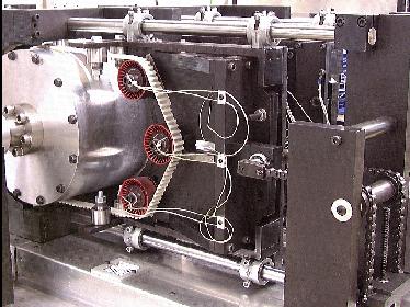
Detail of 1 of the 4 bearing test stations showing
3 pulley bearing assemblies under test.
|
|
|
Description
-
The Bearing Test Rig, specially designed and constructed, enables testing of 12 pulley-bearing assemblies
at temperatures ranging from ambient up to 180°C
at rotational speeds of up to 45,000 rpm and
at loads of between 1000 and 6000N.
-
The test rig consists of an electric motor coupled to a drum. The bearings under test are clustered in groups of 3 at 4 test stations utilising a belt drive from the drum to each station.
-
A dual purpose thermal enclosure/machine guard covers the test stations during operation. A heat source and controller allow temperature control of the test area.
-
Bearing load is achieved by weights on a lever arm.
-
User-to-machine interface is via a RISC PC which also performs machine control and data logging.
|
|
|
|
Drive Drum
-
The drum is a 300mm diameter hollow aluminium drum approximately 600mm long with a smooth external surface and fitted with aluminium end plates and stainless steel stub shafts. The drum is balanced to ensure smooth running at speeds of up to 5000 rpm. There is a misalignment coupling to the motor.
Thermal Enclosure and Heater
-
The enclosure consists of a double aluminium skin with rockwool insulation between the two skins. The enclosure is in two halves split vertically down the axis of the drum. Four windows and lights allow for observation of the test stations.
-
The heater provides for chamber control up to 180
°
C. Temperature control of +/- 2
0
C up to 150
0
C is achieved.
Instrumentation and Computer Interface
-
1 x rack wired to accept
1 x digital input card
1 x digital output card
4 x quad thermocouple cards
1 x temperature control card
1 x encoder card
1 x instrument power supply
-
Provision for input of trip from external source (volt free contact).
Computer Control and Data Logging
-
By RISC PC, specification:
233 megahertz StrongArm RISC processor;
1.2 gigabyte hard disc; 4 megabyte main memory;
16 megabyte video memory; interface card.
-
Options: Printer. Uninterruptible power supply.
-
There is facility for speed control and temperature control via two analogue
0-10V demand from the computer and 16 x 12Bit channel for logging: 12 for
temperature sensing for parts under test, 2 for ambient temperature, and one
for speed of drum and one for drum torque.
-
A further 12 thermocouples can be provided to monitor temperature in the
vicinity of each bearing if this is required.
|
|
-
Thermocouples are monitored continually during the test. When a temperature changes more than an operator-set amount the point is logged.
-
An over temperature trip in software can be selected on any or all channels
-
Recorded data is displayed as temperature viz time graphs. The screen is divided into 4 quarters. Each quarter shows a graph representing one test station; it displays 3 traces, one per bearing, and covers the latest test data. Clicking on a 'history' button displays historical graphical data for each test station.
-
The screen also displays the total number of hours the test has run, drum speed, % completion of test, estimated time to completion, ambient temperature 1 and ambient temperature 2.
-
All data is stored in CSV format to allow export to data analysis and display software packages.
-
Machine and test control is from a block program option, enabling manoeuvres to be combined as blocks and then blocks selected as a sequence with the required number of repeats per block
-
Tests are started, stopped or paused from mouse-selectable on-screen buttons. A 'jog' facility allows the operator to run the drum at low speeds to ensure the belts are running true.
|
|
|
|
|
|
|
|
|
|
|
Pulley-bearing test rigs manufactured by
Si-Plan Electronics Research are in use in
|
|
|
|
|
|
|
|
|
|
Special requirements
Si-Plan Electronics Research Ltd has a history of building special rigs to
customer requirements. The company is able to carry over this service to
its standard product range, giving a flexibility to meet the needs of each
customer - and in-house CAD systems and CNC machining
mean a realistic delivery time will be achieved.
|
|
|
|
|
|
|
|
|
|
|
|
|
|
|
|
|

|
|
|
|
|
|
Bearing test rig with thermal covers removed.
|
|
|
|
|
|
|
|
|
|
|
|
|
|
|
|
Bearing Test Rig dimensions
        Overall dimensions	Test table dimensions
        Height	1500mm		Height	700mm
        Width	1512mm		Width	920mm
        Length	1900mm		Length	1900mm
Bearing Test Rig
	Main drive motor
		2 pole 7.5kW AC vector motor

	Heater elements
		6 x 1.5kW  (Test enclosure operating temperatures up to 180°C)

	Drive drum
		Diameter			300mm
		Length				600mm
		Maximum speed			5000 rpm

	Test stations
		Number of test stations		4
		Maximum travel of test station
			By adjustment		170mm
			By lever movement	10mm
		Number of pulleys per station	3
		Pulley mounting thread size	M8 x 1.25 and M10 x 1.5
		Minimum load at station		1000N
		Maximum load at station		6000N

	Pulley dimensions
		Minimum diameter		45mm
		Maximum diameter		108mm
		Minimum width			20mm
		Maximum width			40mm
		Minimum offset			10mm
		Maximum offset			40mm

	Belt dimensions
		Minimum width			20mm
		Maximum width			40mm
		Minimum length			1170mm
	Maximum length 1545mm (15mm from limit of test station travel)

	Lever arms
		Working length			1600mm
		Lever ratio			20:1
		Travel				200mm (at weight hanger)
|
|
|
|
|
